NEET-XII-Physics
31: Capacitors
Note: Please signup/signin free to get personalized experience.
Note: Please signup/signin free to get personalized experience.
10 minutes can boost your percentage by 10%
Note: Please signup/signin free to get personalized experience.
- Qstn #13Each of the capacitors shown in figure (31-E6) has a capacitance of 2 µF. find the equivalent capacitance of the assembly between the points A and B. Suppose, a battery of emf 60 volts is connected between A and B. Find the potential difference appearing on the individual capacitors.
Figure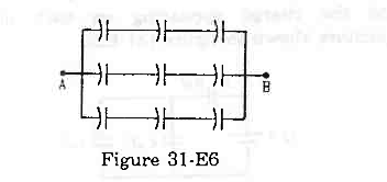 Ans : There are three rows of capacitors connected in parallel in the given system. In each row, three capacitors of capacitance 2 μF are connected in series.
For each row, the equivalent capacitance is given by
`` \frac{1}{{C}_{\,\mathrm{\,r\,}}}=\frac{1}{2}+\frac{1}{2}+\frac{1}{2}``
`` \Rightarrow {C}_{\,\mathrm{\,r\,}}=\frac{2}{3}\,\mathrm{\,\mu F\,}``
As three rows are connected in parallel, their equivalent capacitance is given by
Ceq = Cr + Cr + Cr = `` \frac{2}{3}+\frac{2}{3}+\frac{2}{3}`` = 2 μF
The voltage across each row is the same and is equal to 60 V.
As all capacitors have the same capacitance in each row, the potential difference across their plates is the same.
∴ Potential difference across each capacitor = 20 V
Page No 166:
- Qstn #14It is required to construct a 10 µF capacitor which can be connected across a 200 V battery. Capacitors of capacitance 10 µF are available but they can withstand only 50 V. Design a combination which can yield the desired result.Ans : Let the number of capacitors in series (connected in a row) be x.
The maximum voltage that the capacitors can withstand is 50 V.
The voltage across each row should be equal to 200 V.
Therefore,
x × 50 = 200
Thus,
x = 4 capacitors
Now,
Let there be y such rows.
So, the equivalent capacitance of the combination will be xy.
⇒ xy = 10
⇒ y = 10 x = 4 capacitors
Thus, to yield the required result, the combination of 4 rows, each of 4 capacitors having capacitance 10 µF and breakdown voltage 50 V, is required.
Page No 166:
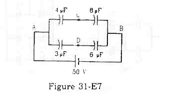

- #15-aFind the potentials at the points C and D.Ans : The capacitance of the two rows connected in parallel is given by
`` {C}_{1}=\frac{4\times 8}{4+8}=\frac{8}{3}\,\mathrm{\,\mu F\,}`` and `` {C}_{2}=\frac{3\times 6}{3+6}=\frac{18}{9}\,\mathrm{\,\mu F\,}=2\,\mathrm{\,\mu F\,}``
As the two rows are in parallel, the potential difference across each row is the same and is equal to 50 V.
The charge on the branch ACB with capacitance `` \frac{8}{3}\,\mathrm{\,\mu F\,}`` is given by
Q = `` \left(\frac{8}{3}\,\mathrm{\,\mu F\,}\right)``×(50 V) = `` \frac{400}{3}\,\mathrm{\,\mu C\,}``
The charge on the branch ADB with capacitance `` 2\,\mathrm{\,\mu F\,}`` is given by
`` Q=C\times V``
`` Q=2\,\mathrm{\,\mu F\,}\times 50=100\,\mathrm{\,\mu C\,}``
The potential at point D is given by
`` {V}_{\,\mathrm{\,D\,}}=\frac{q}{{\,\mathrm{\,C\,}}_{1}}=\frac{100\,\mathrm{\,\mu C\,}}{6\,\mathrm{\,\mu F\,}}``
`` {V}_{\,\mathrm{\,D\,}}=\frac{50}{3}\,\mathrm{\,V\,}``
Similarly, the potential at point C is given by
`` {V}_{\,\mathrm{\,C\,}}=\frac{50}{3}\,\mathrm{\,V\,}``
- #15-bIf a capacitor is connected between C and D, what charge will appear on this capacitor?
FigureAns : As the potential difference between points C and D is zero, the bridge remains balanced and no charge flows from C to D. If a capacitor is connected between points C and D, then the change on the capacitor will be zero.
Page No 166:
- Qstn #16Find the equivalent capacitance of the system shown in figure (31-E8) between the points a and b.
Figure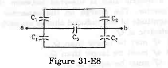 Ans : Capacitors C1 and C2 above and below ab are connected in series and in parallel with C3.
Thus, the equivalent capacitor between a and b is given by
`` {C}_{\,\mathrm{\,eq\,}}=\left(\frac{{C}_{1}{C}_{2}}{{C}_{1}+{C}_{2}}+{C}_{3}+\frac{{C}_{1}{C}_{2}}{{C}_{1}+{C}_{2}}\right)``
`` \Rightarrow {C}_{\,\mathrm{\,eq\,}}={C}_{3}+\frac{2{C}_{1}{C}_{2}}{{C}_{1}+{C}_{2}}``
Page No 166:
- Qstn #17A capacitor is made of a flat plate of area A and a second plate having a stair-like structure as shown in figure (31-E9). The width of each stair is a and the height is b. Find the capacitance of the assembly.
Figure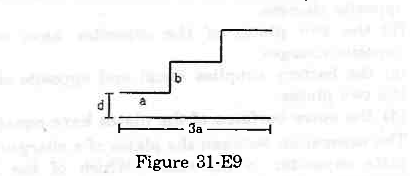 Ans :
Ans :
The total area of the flat plate is A. The width of each stair is the same. Therefore, the area of the surface of each stair facing the flat plate is the same, that is, `` \frac{A}{3}``.

From the figure, it can be observed that the capacitor assembly is made up of three capacitors. The three capacitors are connected in parallel.
For capacitor C1, the area of the plates is `` \frac{A}{3}`` and the separation between the plates is d.
For capacitor C2, the area of the plates is `` \frac{A}{3}`` and the separation between the plates is (d + b).
For capacitor C3, the area of the plates is `` \frac{A}{3}`` and the separation between the plates is (d + 2b).
Therefore,
`` {C}_{1}=\frac{{\in }_{0}A}{3d}``
`` {C}_{2}=\frac{{\in }_{0}A}{3\left(d+b\right)}``
`` {C}_{3}=\frac{{\in }_{0}A}{3\left(d+2b\right)}``
As the three capacitors are in parallel combination,
`` C={C}_{1}+{C}_{2}+{C}_{3}``
`` \Rightarrow C=\frac{{\in }_{0}A}{3d}+\frac{{\in }_{0}A}{3\left(d+b\right)}+\frac{{\in }_{0}A}{3\left(d+2b\right)}``
`` \Rightarrow C=\frac{{\in }_{0}A}{3}\frac{\left(3{d}^{2}+6bd+2{b}^{2}\right)}{d\left(d+b\right)\left(d+2b\right)}``
Page No 166:
- Qstn #18A cylindrical capacitor is constructed using two coaxial cylinders of the same length 10 cm and of radii 2 mm and 4 mm.
- #18-aCalculate the capacitance.Ans : The capacitance of a cylindrical capacitor is given by
`` C=\frac{2\,\mathrm{\,\pi \,}{\in }_{0}l}{\,\mathrm{\,ln\,}\left({\displaystyle \frac{{R}_{2}}{{R}_{1}}}\right)}``
`` \Rightarrow C=\frac{2\times 3.14\times 8.85\times {10}^{-12}\times 0.10}{\,\mathrm{\,ln\,}2}``
`` \Rightarrow C=8\,\mathrm{\,pF\,}\left(\because \,\mathrm{\,l\,}\,\mathrm{\,n\,}2=0.693\right)``
- #18-bAnother capacitor of the same length is constructed with cylinders of radii 4 mm and 8 mm. Calculate the capacitance.Ans : When a capacitor of the same height with cylinders of radii 4 mm and 8 mm is taken, its capacitance comes to 8 pF, which is the same as above because the ratio of the radii is the same.
Page No 166:
- Qstn #19A 100 pF capacitor is charged to a potential difference of 24 V. It is connected to an uncharged capacitor of capacitance 20 pF. What will be the new potential difference across the 100 pF capacitor?Ans : Given:
`` {C}_{1}=100\,\mathrm{\,pF\,}``
`` V=24\,\mathrm{\,V\,}``
Charge on the given capacitor, `` q={C}_{1}V=24\times 100\,\mathrm{\,pC\,}``
Capacitance of the uncharged capacitor,`` {C}_{2}=20\,\mathrm{\,pF\,}``
When the charged capacitor is connected with the uncharged capacitor, the net charge on the system of the capacitors becomes
`` {q}_{1}+{q}_{2}=24\times 100\,\mathrm{\,qC\,}...\left(\,\mathrm{\,i\,}\right)``
The potential difference across the plates of the capacitors will be the same.
Thus,
`` \frac{{q}_{1}}{{C}_{1}}=\frac{{q}_{2}}{{C}_{2}}``
`` \Rightarrow \frac{{q}_{1}}{100}=\frac{{q}_{2}}{20}``
`` \Rightarrow {q}_{1}=5{q}_{2}...\left(\,\mathrm{\,ii\,}\right)``
From eqs. (i) and (ii), we get
`` {q}_{1}+\frac{{q}_{1}}{5}=24\times 100\,\mathrm{\,pC\,}``
`` \Rightarrow 6{q}_{1}=5\times 24\times 100\,\mathrm{\,pC\,}``
`` \Rightarrow {q}_{1}=\frac{5\times 24\times 100}{6}\,\mathrm{\,pC\,}``
`` \,\mathrm{\,Now\,},``
`` {V}_{1}=\frac{{q}_{1}}{{C}_{1}}``
`` =\frac{5\times 24\times 100\,\mathrm{\,pC\,}}{6\times 100\,\mathrm{\,pF\,}}=20\,\mathrm{\,V\,}``
Page No 166:
- Qstn #20Each capacitor shown in figure (31-E10) has a capacitance of 5⋅0 µF. The emf of the battery is 50 V. How much charge will flow through AB if the switch S is closed?
Figure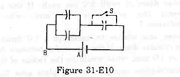 Ans : Initially, when the switch S is open, the equivalent capacitance is given by
`` {C}_{\,\mathrm{\,eq\,}}=\frac{2C\times C}{3\,\mathrm{\,C\,}}``
`` \Rightarrow {C}_{\,\mathrm{\,eq\,}}=\frac{2}{3}C=\frac{2}{3}\times 5.0\,\mathrm{\,\mu F\,}``
The charge supplied by the battery is given by
`` Q={C}_{\,\mathrm{\,eq\,}}\times V``
`` \Rightarrow Q=\frac{2}{3}\times (5.0\,\mathrm{\,\mu F\,})\times (50\,\mathrm{\,V\,})``
`` \Rightarrow Q=\frac{500}{3}\,\mathrm{\,\mu C\,}``
When the switch S is closed, no charge goes to the capacitor connected in parallel with the switch.
Thus, the equivalent capacitance is given by
`` {C}_{\,\mathrm{\,eq\,}}=2C=2\times 5.0=10\,\mathrm{\,\mu F\,}``
The charge supplied by the battery is given by
`` Q=10\,\mathrm{\,\mu F\,}\times 50=500\,\mathrm{\,\mu C\,}``
The initial charge stored in the shorted capacitor starts discharging."?
Hence, the charge that flows from A to B is given by
`` {Q}_{\,\mathrm{\,net\,}}=500\,\mathrm{\,\mu C\,}-\frac{500}{3}\,\mathrm{\,\mu C\,}``
`` \Rightarrow {Q}_{\,\mathrm{\,net\,}}=3.3\times {10}^{-4}\,\mathrm{\,C\,}``
Page No 166:
- Qstn #21The particle P shown in figure (31-E11) has a mass of 10 mg and a charge of -0⋅01 µC. Each plate has a surface area 100 cm2 on one side. What potential difference V should be applied to the combination to hold the particle P in equilibrium?
Figure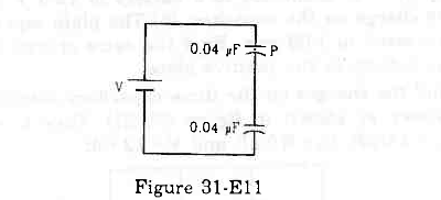 Ans : The particle is balanced when the electrical force on it is balanced by its weight.
Thus,
`` mg=qE``
`` mg=q\times \frac{V\text{'}}{d}...\left(\,\mathrm{\,i\,}\right)``
`` ``
Here,
d = Separation between the plates of the capacitor
V' = Potential difference across the capacitor containing the particle
We know that the capacitance of a capacitor is given by
`` C=\frac{{\in }_{0}A}{d}``
`` \Rightarrow d=\frac{{\in }_{0}A}{C}``
Thus, eq. (i) becomes
`` mg=q\times V\text{'}\times \frac{\,\mathrm{\,C\,}}{{\in }_{0}A}``
`` \Rightarrow V\text{'}=\frac{mg{\in }_{0}A}{q\times C}``
`` \Rightarrow V\text{'}=\frac{{10}^{-6}\times 9.8\times (8.85\times {10}^{-12})\times (100\times {10}^{-4})}{(0.01\times {10}^{-6})\times (0.04\times {10}^{-6})}``
`` \Rightarrow V\text{'}=21.68\,\mathrm{\,mV\,}``
Since the values of both the capacitors are the same,
V = 2V' = 2 `` \times `` 21.86 `` \approx `` 43 mV
Page No 166:
- Qstn #22Both the capacitors shown in figure (31-E12) are made of square plates of edge a. The separations between the plates of the capacitors are d1 and d2 as shown in the figure. A potential difference V is applied between the points a and b. An electron is projected between the plates of the upper capacitor along the central line. With what minimum speed should the electron be projected so that it does not collide with any plate? Consider only the electric forces.
Figure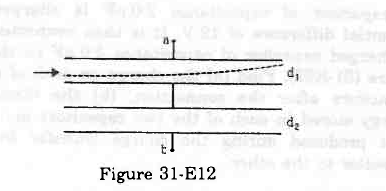 Ans :
Ans :
Let:
Velocity of the electron = u
Mass of the electron = m
Now,
Horizontal distance, x = u × t
`` \Rightarrow t=\frac{x}{v}`` ...(i)
Let the electric field inside the capacitor be E
∴ Acceleration of the electron =`` \frac{qE}{m}``
Vertical distance, `` y=\frac{1}{2}\frac{qE}{m}{t}^{2}=\frac{1}{2}\frac{qE}{m}{\left(\frac{x}{u}\right)}^{2}\left(\because t=\frac{x}{u}\right)``
`` y=\frac{{d}_{1}}{2}\,\mathrm{\,and\,}x=a``
`` \Rightarrow \frac{{d}_{1}}{2}=\frac{1}{2}\frac{qE}{m}·{\left(\frac{a}{u}\right)}^{2}...\left(\,\mathrm{\,ii\,}\right)``
Capacitance of the two capacitors:
C1 = `` \frac{{\in }_{0}{a}^{2}}{{d}_{1}}`` and C2 = `` \frac{{\in }_{0}{a}^{2}}{{d}_{2}}``
It is given that the capacitors are connected in series.
Thus, the equivalent capacitance is given by
`` {C}_{\,\mathrm{\,eq\,}}=\frac{{C}_{1}{C}_{2}}{{C}_{1}+{C}_{2}}``
`` {C}_{\,\mathrm{\,eq\,}}=\frac{{\displaystyle \frac{{\in }_{0}{a}^{2}}{{d}_{1}}}\times {\displaystyle \frac{{\in }_{0}{a}^{2}}{{d}_{2}}}}{{\displaystyle \frac{{\in }_{0}{a}^{2}}{{d}_{1}}}+{\displaystyle \frac{{\in }_{0}{a}^{2}}{{d}_{2}}}}=\frac{{\in }_{0}{a}^{2}}{\left({d}_{1}+{d}_{2}\right)}``
Total charge on the system of capacitors, Q = CeqV = `` \frac{{\in }_{0}{a}^{2}}{\left({d}_{1}+{d}_{2}\right)}V``
As the capacitors are in series, charge on both of them is the same.
The potential difference across the capacitor containing the electron is given by
`` V=\frac{Q}{{C}_{1}}=\frac{{\in }_{0}{a}^{2}V}{{C}_{1}\left({d}_{1}+{d}_{2}\right)}=\frac{{\in }_{0}{a}^{2}V}{\left({\displaystyle \frac{{\in }_{0}{a}^{2}}{{d}_{1}}}\right)\left({d}_{1}+{d}_{2}\right)}=\frac{V{d}_{1}}{{d}_{1}+{d}_{2}}``
The magnitude of the electric field inside the capacitor is given by
`` E=\frac{V}{{d}_{1}}=\frac{V}{{d}_{1}+{d}_{2}}``
The charge on electron q is represented by e.
On putting the values of q and E in (ii), we get
`` \Rightarrow \frac{{d}_{1}}{2}=\frac{1}{2}\frac{qV}{m({d}_{1}+{d}_{2})}·{\left(\frac{a}{u}\right)}^{2}...\left(\,\mathrm{\,iii\,}\right)``
The minimum velocity of the electron is given by
`` u={\left(\frac{Ve{a}^{2}}{m{d}_{1}\left({d}_{1}+{d}_{2}\right)}\right)}^{1/2}``
Page No 167:
- Qstn #23The plates of a capacitor are 2⋅00 cm apart. An electron-proton pair is released somewhere in the gap between the plates and it is found that the proton reaches the negative plate at the same time as the electron reaches the positive plate. At what distance from the negative plate was the pair released?Ans : Let the electric field inside the capacitor be E.
Now,
Magnitude of acceleration of the electron, `` {a}_{\,\mathrm{\,e\,}}=\frac{{q}_{\,\mathrm{\,e\,}}E}{{m}_{\,\mathrm{\,e\,}}}``
Magnitude of acceleration of the proton, `` {a}_{\,\mathrm{\,p\,}}=\frac{{q}_{\,\mathrm{\,p\,}}E}{{m}_{\,\mathrm{\,p\,}}}``
Let t be the time taken by the electron and proton to reach the positive and negative plates, respectively.
The initial velocities of the proton and electron are zero.
Thus, the distance travelled by the proton is given by
`` x=\frac{1}{2}\frac{{q}_{\,\mathrm{\,p\,}}E}{{m}_{\,\mathrm{\,p\,}}}{t}^{2}`` ...(1)
And, the distance travelled by the electron is given by
`` 2-x=\frac{1}{2}\frac{{q}_{\,\mathrm{\,e\,}}E}{{m}_{\,\mathrm{\,e\,}}}{t}^{2}`` ...(2)
On dividing (1) by (2), we get
`` \frac{x}{2-x}=\frac{\left({\displaystyle \frac{{q}_{\,\mathrm{\,p\,}}E}{{m}_{\,\mathrm{\,p\,}}}}\right)}{\left({\displaystyle \frac{{q}_{\,\mathrm{\,e\,}}E}{{m}_{\,\mathrm{\,e\,}}}}\right)}=\frac{{m}_{\,\mathrm{\,e\,}}}{{m}_{\,\mathrm{\,p\,}}}=\frac{9.1\times {10}^{-31}}{1.67\times {10}^{-27}}=5.449\times {10}^{-4}``
`` \Rightarrow x=10.898\times {10}^{-4}-5.449\times {10}^{-4}x``
`` \Rightarrow x=\frac{10.898\times {10}^{-4}}{1.0005449}=1.08\times {10}^{-8}\,\mathrm{\,cm\,}``
Page No 167: