NEET-XII-Physics
06: Electromagnetic Induction
Note: Please signup/signin free to get personalized experience.
Note: Please signup/signin free to get personalized experience.
10 minutes can boost your percentage by 10%
Note: Please signup/signin free to get personalized experience.
- #Chapter 6 - Electromagnetic Induction
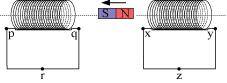
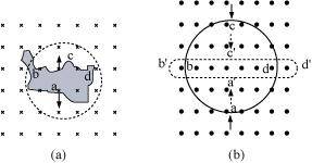
- Qstn #1Predict the direction of induced current in the situations described by the following Figs. 6.18(a) to (f ).
Ans : The direction of the induced current in a closed loop is given by Lenz’s law. The given pairs of figures show the direction of the induced current when the North pole of a bar magnet is moved towards and away from a closed loop respectively.
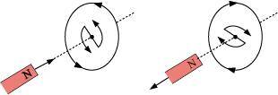
Using Lenz’s rule, the direction of the induced current in the given situations can be predicted as follows:
- #1-a
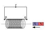
Ans : The direction of the induced current is along qrpq.
- #1-b
Ans : The direction of the induced current is along prqp.
- #1-c
Ans : The direction of the induced current is along yzxy.
- #1-d
Ans : The direction of the induced current is along zyxz.
- #1-e
Ans : The direction of the induced current is along xryx.
- #1-f
Ans : No current is induced since the field lines are lying in the plane of the closed loop.
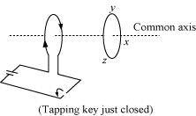
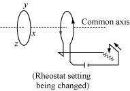
- Qstn #2Use Lenz’s law to determine the direction of induced current in the situations described by Fig. 6.19:
Ans : According to Lenz’s law, the direction of the induced emf is such that it tends to produce a current that opposes the change in the magnetic flux that produced it.
- #2-aA wire of irregular shape turning into a circular shape;Ans : When the shape of the wire changes, the flux piercing through the unit surface area increases. As a result, the induced current produces an opposing flux. Hence, the induced current flows along adcb.
- #2-bA circular loop being deformed into a narrow straight wire.
Ans : When the shape of a circular loop is deformed into a narrow straight wire, the flux piercing the surface decreases. Hence, the induced current flows along
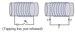
- Qstn #3A long solenoid with 15 turns per cm has a small loop of area 2.0 cm2 placed inside the solenoid normal to its axis. If the current carried by the solenoid changes steadily from 2.0 A to 4.0 A in 0.1 s, what is the induced emf in the loop while the current is changing?
Ans : Number of turns on the solenoid = 15 turns/cm = 1500 turns/m
Number of turns per unit length, n = 1500 turns
The solenoid has a small loop of area, A = 2.0 cm2 = 2 × 10⁻⁴ m2
Current carried by the solenoid changes from 2 A to 4 A.
 Change in current in the solenoid, di = 4 - 2 = 2 A
Change in time, dt = 0.1 s
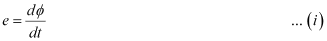
Induced emf in the solenoid is given by Faraday’s law as:
Where,
 = Induced flux through the small loop
= BA ... (ii)
B = Magnetic field
=
μ0 = Permeability of free space
= 4``\pi``×10-7 H/m
Hence, equation (i) reduces to:
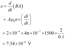
Hence, the induced voltage in the loop is
- Qstn #4A rectangular wire loop of sides 8 cm and 2 cm with a small cut is moving out of a region of uniform magnetic field of magnitude 0.3 T directed normal to the loop. What is the emf developed across the cut if the velocity of the loop is 1 cm s-1 in a direction normal to the (a) longer side, (b) shorter side of the loop? For how long does the induced voltage last in each case?
Ans : Length of the rectangular wire, l = 8 cm = 0.08 m
Width of the rectangular wire, b = 2 cm = 0.02 m
Hence, area of the rectangular loop,
A = lb
= 0.08 × 0.02
= 16 × 10-4 m2
Magnetic field strength, B = 0.3 T
Velocity of the loop, v = 1 cm/s = 0.01 m/s
(a) Emf developed in the loop is given as:
e = Blv
= 0.3 × 0.08 × 0.01 = 2.4 × 10⁻⁴ V

Hence, the induced voltage is 2.4 × 10⁻⁴ V which lasts for 2 s.
(b) Emf developed, e = Bbv
= 0.3 × 0.02 × 0.01 = 0.6 × 10⁻⁴ V
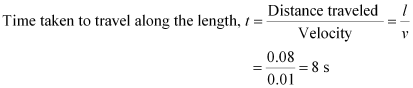
Hence, the induced voltage is 0.6 × 10⁻⁴ V which lasts for 8 s.
- Qstn #5A 1.0 m long metallic rod is rotated with an angular frequency of 400 rad s-1 about an axis normal to the rod passing through its one end. The other end of the rod is in contact with a circular metallic ring. A constant and uniform magnetic field of 0.5 T parallel to the axis exists everywhere. Calculate the emf developed between the centre and the ring.
Ans : Length of the rod, l = 1 m
Angular frequency,ω = 400 rad/s
Magnetic field strength, B = 0.5 T
One end of the rod has zero linear velocity, while the other end has a linear velocity of lω.
Average linear velocity of the rod,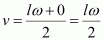
Emf developed between the centre and the ring,
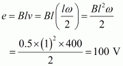
Hence, the emf developed between the centre and the ring is 100 V.
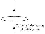
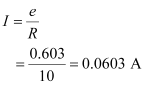
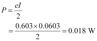
- Qstn #6A circular coil of radius 8.0 cm and 20 turns is rotated about its vertical diameter with an angular speed of 50 rad s-1 in a uniform horizontal magnetic field of magnitude 3.0×10⁻² T. Obtain the maximum and average emf induced in the coil. If the coil forms a closed loop of resistance 10``\Omega``, calculate the maximum value of current in the coil. Calculate the average power loss due to Joule heating. Where does this power come from?
Ans : Max induced emf = 0.603 V
Average induced emf = 0 V
Max current in the coil = 0.0603 A
Average power loss = 0.018 W
(Power comes from the external rotor)
Radius of the circular coil, r = 8 cm = 0.08 m
Area of the coil, A = ``\pi``r2 = ``\pi`` × (0.08)2 m2
Number of turns on the coil, N = 20
Angular speed, ω = 50 rad/s
Magnetic field strength, B = 3 × 10⁻² T
Resistance of the loop, R = 10 ``\Omega``
Maximum induced emf is given as:
e = Nω AB
= 20 × 50 × ``\pi`` × (0.08)2 × 3 × 10-2
= 0.603 V
The maximum emf induced in the coil is 0.603 V.
Over a full cycle, the average emf induced in the coil is zero.
Maximum current is given as:
Average power loss due to joule heating:
The current induced in the coil produces a torque opposing the rotation of the coil. The rotor is an external agent. It must supply a torque to counter this torque in order to keep the coil rotating uniformly. Hence, dissipated power comes from the external rotor.