NEET-XII-Physics
03: Current Electricity
Note: Please signup/signin free to get personalized experience.
Note: Please signup/signin free to get personalized experience.
10 minutes can boost your percentage by 10%
Note: Please signup/signin free to get personalized experience.
- #Chapter 3 - Current Electricity
- Qstn #1The storage battery of a car has an emf of 12 V. If the internal resistance of the battery is 0.4``\Omega``, what is the maximum current that can be drawn from the battery?
Ans : Emf of the battery, E = 12 V
Internal resistance of the battery, r = 0.4 ``\Omega``
Maximum current drawn from the battery = I
According to Ohm’s law,
The maximum current drawn from the given battery is 30 A.
- Qstn #2A battery of emf 10 V and internal resistance 3 ``\Omega`` is connected to a resistor. If the current in the circuit is 0.5 A, what is the resistance of the resistor? What is the terminal voltage of the battery when the circuit is closed?
Ans : Emf of the battery, E = 10 V
Internal resistance of the battery, r = 3 ``\Omega``
Current in the circuit, I = 0.5 A
Resistance of the resistor = R
The relation for current using Ohm’s law is,
Terminal voltage of the resistor = V
According to Ohm’s law,
V = IR
= 0.5 × 17
= 8.5 V
Therefore, the resistance of the resistor is 17 ``\Omega`` and the terminal voltage is
8.5 V.
- #3
- #3-aThree resistors 1 ``\Omega``, 2 ``\Omega``, and 3 ``\Omega`` are combined in series. What is the total resistance of the combination?Ans : Three resistors of resistances 1 ``\Omega``, 2 ``\Omega``, and 3 ``\Omega`` are combined in series. Total resistance of the combination is given by the algebraic sum of individual resistances.
Total resistance = 1 + 2 + 3 = 6 ``\Omega``
- #3-bIf the combination is connected to a battery of emf 12 V and negligible internal resistance, obtain the potential drop across each resistor.Ans : Current flowing through the circuit = I
Emf of the battery, E = 12 V
Total resistance of the circuit, R = 6 ``\Omega``
The relation for current using Ohm’s law is,

Potential drop across 1 ``\Omega`` resistor = V1
From Ohm’s law, the value of V1 can be obtained as
V1 = 2 × 1= 2 V ... (i)
Potential drop across 2 ``\Omega`` resistor = V2
Again, from Ohm’s law, the value of V2 can be obtained as
V2 = 2 × 2= 4 V ... (ii)
Potential drop across 3 ``\Omega`` resistor = V3
Again, from Ohm’s law, the value of V3 can be obtained as
V3 = 2 × 3= 6 V ... (iii)
Therefore, the potential drop across 1 ``\Omega``, 2 ``\Omega``, and 3 ``\Omega`` resistors are 2 V, 4 V, and 6 V respectively.
- #4
- #4-aThree resistors 2 ``\Omega``, 4 ``\Omega`` and 5 ``\Omega`` are combined in parallel. What is the total resistance of the combination?Ans : There are three resistors of resistances,
R1 = 2 ``\Omega``, R2 = 4 ``\Omega``, and R3 = 5 ``\Omega``
They are connected in parallel. Hence, total resistance (R) of the combination is given by,
Therefore, total resistance of the combination is .
.
- #4-bIf the combination is connected to a battery of emf 20 V and negligible internal resistance, determine the current through each resistor, and the total current drawn from the battery.Ans : Emf of the battery, V = 20 V
Current (I1) flowing through resistor R1 is given by,

Current (I2) flowing through resistor R2 is given by,

Current (I3) flowing through resistor R3 is given by,

Total current, I = I1 + I2 + I3 = 10 + 5 + 4 = 19 A
Therefore, the current through each resister is 10 A, 5 A, and 4 A respectively and the total current is 19 A.
- Qstn #5At room temperature (27.0 °C) the resistance of a heating element is 100 ``\Omega``. What is the temperature of the element if the resistance is found to be 117 ``\Omega``, given that the temperature coefficient of the material of the resistor is

Ans : Room temperature, T = 27°C
Resistance of the heating element at T, R = 100 ``\Omega``
Let T1 is the increased temperature of the filament.
Resistance of the heating element at T1, R1 = 117 ``\Omega``
Temperature co-efficient of the material of the filament,
Therefore, at 1027°C, the resistance of the element is 117``\Omega``.
- Qstn #6A negligibly small current is passed through a wire of length 15 m and uniform cross-section 6.0 × 10⁻⁷ m2, and its resistance is measured to be 5.0 ``\Omega``. What is the resistivity of the material at the temperature of the experiment?
Ans : Length of the wire, l =15 m
Area of cross-section of the wire, a = 6.0 × 10⁻⁷ m2
Resistance of the material of the wire, R = 5.0 ``\Omega``
Resistivity of the material of the wire = ``\rho``
Resistance is related with the resistivity as
Therefore, the resistivity of the material is 2 × 10⁻⁷ ``\Omega`` m.
- Qstn #7A silver wire has a resistance of 2.1 ``\Omega`` at 27.5 °C, and a resistance of 2.7 ``\Omega`` at 100 °C. Determine the temperature coefficient of resistivity of silver.
Ans : Temperature, T1 = 27.5°C
Resistance of the silver wire at T1, R1 = 2.1 ``\Omega``
Temperature, T2 = 100°C
Resistance of the silver wire at T2, R2 = 2.7 ``\Omega``
Temperature coefficient of silver = α
It is related with temperature and resistance as
Therefore, the temperature coefficient of silver is 0.0039°C-1.
- Qstn #8Aheating element using nichrome connected to a 230 V supply draws an initial current of 3.2 A which settles after a few seconds toa steady value of 2.8 A. What is the steady temperature of the heating element if the room temperature is 27.0 °C? Temperature coefficient of resistance of nichrome averaged over the temperature range involved is 1.70 × 10⁻⁴ °C -1.
Ans : Supply voltage, V = 230 V
Initial current drawn, I1 = 3.2 A
Initial resistance = R1, which is given by the relation,
Steady state value of the current, I2 = 2.8 A
Resistance at the steady state = R2, which is given as
Temperature co-efficient of nichrome, α = 1.70 × 10⁻⁴ °C -1
Initial temperature of nichrome, T1= 27.0°C
Study state temperature reached by nichrome = T2
T2 can be obtained by the relation for α,
Therefore, the steady temperature of the heating element is 867.5°C
- Qstn #9Determine the current in each branch of the network shown in fig 3.30:
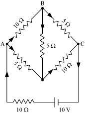
Ans : Current flowing through various branches of the circuit is represented in the given figure.
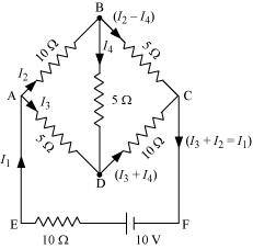
I1 = Current flowing through the outer circuit
I2 = Current flowing through branch AB
I3 = Current flowing through branch AD
I2 - I4 = Current flowing through branch BC
I3 + I4 = Current flowing through branch CD
I4 = Current flowing through branch BD
For the closed circuit ABDA, potential is zero i.e.,
10I2 + 5I4 - 5I3 = 0
2I2 + I4 -I3 = 0
I3 = 2I2 + I4 ... (1)
For the closed circuit BCDB, potential is zero i.e.,
5(I2 - I4) - 10(I3 + I4) - 5I4 = 0
5I2 + 5I4 - 10I3 - 10I4 - 5I4 = 0
5I2 - 10I3 - 20I4 = 0
I2 = 2I3 + 4I4 ... (2)
For the closed circuit ABCFEA, potential is zero i.e.,
-10 + 10 (I1) + 10(I2) + 5(I2 - I4) = 0
10 = 15I2 + 10I1 - 5I4
3I2 + 2I1 - I4 = 2 ... (3)
From equations (1) and (2), we obtain
I3 = 2(2I3 + 4I4) + I4
I3 = 4I3 + 8I4 + I4
- 3I3 = 9I4
- 3I4 = + I3 ... (4)
Putting equation (4) in equation (1), we obtain
I3 = 2I2 + I4
- 4I4 = 2I2
I2 = - 2I4 ... (5)
It is evident from the given figure that,
I1 = I3 + I2 ... (6)
Putting equation (6) in equation (1), we obtain
3I2 +2(I3 + I2) - I4 = 2
5I2 + 2I3 - I4 = 2 ... (7)
Putting equations (4) and (5) in equation (7), we obtain
5(-2 I4) + 2(- 3 I4) - I4 = 2
- 10I4 - 6I4 - I4 = 2
17I4 = - 2

Equation (4) reduces to
I3 = - 3(I4)
Therefore, current in branch
In branch BC =
In branch CD =
In branch AD
In branch BD =
Total current =
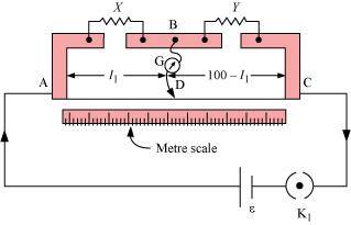
- #10Ans : A metre bridge with resistors X and Y is represented in the given figure.