NEET-XII-Physics
pp year:2018
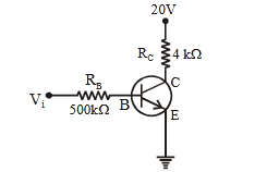
- #6In the circuit shown in the figure, the input
voltage``V_i`` is 20 V, ``V_{BE}`` = 0 and
``V_{CE}`` = 0. The values of ``I_B``, ``I_C``
and ``\beta`` are given by :-
(1) ``I_B``= 40 ``\mu A``, ``I_C``= 10 mA, ``\beta``= 250
(2) ``I_B``= 25 ``\mu A``, ``I_C``= 5 mA, ``\beta``= 200
(3) ``I_B``= 20 ``\mu A``, ``I_C``= 5 mA, ``\beta``= 250
(4) ``I_B``= 40 ``\mu A``, ``I_C``= 5 mA, ``\beta``= 125digAnsr: 4Ans : (4)
Sol. Vi = IBRB + VBE
20 = IB × (500 × 10
3) + 0
= =
B 3
20
I 40µA
500 10
= +CC C C CEV I R V
20 = IC × (4 × 10
3) + 0
IC = 5 × 10
-3 = 5 mA
= = =
3
C
6
B
I 5 10
125
I 40 10