NEET-XII-Physics
07: Alternating Current
Note: Please signup/signin free to get personalized experience.
Note: Please signup/signin free to get personalized experience.
10 minutes can boost your percentage by 10%
Note: Please signup/signin free to get personalized experience.
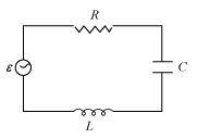
- Qstn #11Figure 7.21 shows a series LCR circuit connected to a variable frequency 230 V source. L = 5.0 H, C = 80μF, R = 40 ``\Omega``
Ans : Inductance of the inductor, L = 5.0 H
Capacitance of the capacitor, C = 80 μF = 80 × 10-6 F
Resistance of the resistor, R = 40 ``\Omega``
Potential of the variable voltage source, V = 230 V
- #11-aDetermine the source frequency which drives the circuit in resonance.Ans : Resonance angular frequency is given as:
Hence, the circuit will come in resonance for a source frequency of 50 rad/s.
- #11-bObtain the impedance of the circuit and the amplitude of current at the resonating frequency.Ans : Impedance of the circuit is given by the relation,
.gif)
At resonance,

Amplitude of the current at the resonating frequency is given as:
Where,
V0 = Peak voltage
Hence, at resonance, the impedance of the circuit is 40 ``\Omega`` and the amplitude of the current is 8.13 A.
- #11-cDetermine the rms potential drops across the three elements of the circuit. Show that the potential drop across the LC combination is zero at the resonating frequency.Ans : Rms potential drop across the inductor,
(VL)rms = I × ωRL
Where,
I = rms current
Potential drop across the capacitor,
Potential drop across the resistor,
(VR)rms = IR
= × 40 = 230 V
Potential drop across the LC combination,
At resonance,
∴VLC= 0
Hence, it is proved that the potential drop across the LC combination is zero at resonating frequency.
- Qstn #12An LC circuit contains a 20 mH inductor and a 50 μF capacitor with an initial charge of 10 mC. The resistance of the circuit is negligible. Let the instant the circuit is closed be t = 0.
Ans : Inductance of the inductor, L = 20 mH = 20 × 10-3 H
Capacitance of the capacitor, C = 50 μF = 50 × 10-6 F
Initial charge on the capacitor, Q = 10 mC = 10 × 10-3 C
- #12-aWhat is the total energy stored initially? Is it conserved during LC oscillations?Ans : Total energy stored initially in the circuit is given as:
Hence, the total energy stored in the LC circuit will be conserved because there is no resistor connected in the circuit.
- #12-bWhat is the natural frequency of the circuit?Ans : Natural frequency of the circuit is given by the relation,
Natural angular frequency,

Hence, the natural frequency of the circuit is 103 rad/s.
- #12-cAt what time is the energy stored
- #12-c-icompletely electrical (i.e., stored in the capacitor)? (ii) completely magnetic (i.e., stored in the inductor)?Ans : For time period (T
 ), total charge on the capacitor at time t,
For energy stored is electrical, we can write Q’ = Q.
Hence, it can be inferred that the energy stored in the capacitor is completely electrical at time, t =
(ii) Magnetic energy is the maximum when electrical energy, Q′ is equal to 0.
Hence, it can be inferred that the energy stored in the capacitor is completely magnetic at time,
- #12-dAt what times is the total energy shared equally between the inductor and the capacitor?Ans : Q1 = Charge on the capacitor when total energy is equally shared between the capacitor and the inductor at time t.
When total energy is equally shared between the inductor and capacitor, the energy stored in the capacitor = (maximum energy).
Hence, total energy is equally shared between the inductor and the capacity at time,
- #12-eIf a resistor is inserted in the circuit, how much energy is eventually dissipated as heat?Ans : If a resistor is inserted in the circuit, then total initial energy is dissipated as heat energy in the circuit. The resistance damps out the LC oscillation.
- Qstn #13A coil of inductance 0.50 H and resistance 100 ``\Omega`` is connected to a 240 V, 50 Hz ac supply.
Ans : Inductance of the inductor, L = 0.50 H
Resistance of the resistor, R = 100 ``\Omega``
Potential of the supply voltage, V = 240 V
Frequency of the supply, ν = 50 Hz
- #13-aWhat is the maximum current in the coil?Ans : Peak voltage is given as:

Angular frequency of the supply,
ω = 2 ``\pi``ν
= 2``\pi`` × 50 = 100 ``\pi`` rad/s
Maximum current in the circuit is given as:

- #13-bWhat is the time lag between the voltage maximum and the current maximum?Ans : Equation for voltage is given as:
V = V0 cos ωt
Equation for current is given as:
I = I0 cos (ωt - Φ)
Where,
Φ = Phase difference between voltage and current
At time, t = 0.
V = V0(voltage is maximum)
Forωt - Φ = 0 i.e., at time ,
,
I = I0 (current is maximum)
Hence, the time lag between maximum voltage and maximum current is .
.
Now, phase angle Φis given by the relation,
Hence, the time lag between maximum voltage and maximum current is 3.2 ms.
- Qstn #14Obtain the answers (a) to (b) in Exercise 7.13 if the circuit is connected to a high frequency supply (240 V, 10 kHz). Hence, explain the statement that at very high frequency, an inductor in a circuit nearly amounts to an open circuit. How does an inductor behave in a dc circuit after the steady state?
Ans : Inductance of the inductor, L = 0.5 Hz
Resistance of the resistor, R = 100 ``\Omega``
Potential of the supply voltages, V = 240 V
Frequency of the supply,ν = 10 kHz = 104 Hz
Angular frequency, ω = 2``\pi``ν= 2``\pi`` × 104 rad/s
(a) Peak voltage,
Maximum current,
(b) For phase differenceΦ, we have the relation:
It can be observed that I0 is very small in this case. Hence, at high frequencies, the inductor amounts to an open circuit.
In a dc circuit, after a steady state is achieved, ω = 0. Hence, inductor L behaves like a pure conducting object.