CBSE-XI-Physics
38: Electromagnetic Induction
Note: Please signup/signin free to get personalized experience.
Note: Please signup/signin free to get personalized experience.
10 minutes can boost your percentage by 10%
Note: Please signup/signin free to get personalized experience.
- Qstn #12Consider the self-inductance per unit length of a solenoid at its centre and that near its ends. Which of the two is greater?Ans : Self-inductance per unit length of solenoid is given as,
`` \frac{L}{l}={\mu }_{0}{n}^{2}A``
From the above equation we can see that, self inductance per unit length will depend on the permeability of free space (`` {\mu }_{0}``), number of turns per unit length (n) and area of the cross-section of the solenoid (A). All the above factors are constant at the centre and near any end of the solenoid therefore self inductance at both the points will be same.
Page No 304:
- Qstn #13Consider the energy density in a solenoid at its centre and that near its ends. Which of the two is greater?Ans : In a solenoid energy is stored in the form of magnetic field. If a constant current is flowing from a solenoid then magnetic field inside the solenoid is uniform. Therefore, energy per unit volume (or energy density) in the magnetic field inside the solenoid is constant.
The energy per unit volume in the magnetic field is given as,
`` u=\frac{B}{2{\mu }_{0}}``, where B is uniform magnetic field inside the solenoid.
Therefore, energy density all points inside a solenoid is same.
Page No 304:
- #Section : ii
- Qstn #1A rod of length l rotates with a small but uniform angular velocity ω about its perpendicular bisector. A uniform magnetic field B exists parallel to the axis of rotation. The potential difference between the centre of the rod and an end is
(a) zero
(b)
18ωBl2
(c)
12ωBl2
(d) Bωl2.digAnsr: bAns : (b) `` \frac{1}{8}\,\mathrm{\,\omega \,}B{l}^{2}``

Let us consider a small element dx at a distance x from the centre of the rod rotating with angular velocity ω about its perpendicular bisector. The emf induced in the rod because of this small element is given by
`` de=Bvl=B\omega xdx``
The emf induced across the centre and end of the rod is given by
`` \int de={\int }_{0}^{l/2}B\omega xdx``
`` \Rightarrow E=B\omega {\left[\frac{{x}^{2}}{2}\right]}_{0}^{l/2}``
`` \Rightarrow E=\frac{1}{8}B\omega {l}^{2}``
Page No 304:
- Qstn #2A rod of length l rotates with a uniform angular velocity ω about its perpendicular bisector. A uniform magnetic field B exists parallel to the axis of rotation. The potential difference between the two ends of the rod is
(a) zero
(b)
12Blω2
(c) Blω2
(d) 2Blω2.digAnsr: aAns : (a) zero

Let us consider a small element dx at a distance x from the centre of the rod rotating with angular velocity ω about its perpendicular bisector. The emf induced in the small element of the rod because of its motion is given by
`` de=B\omega xdx``
The emf induced between the centre of the rod and one of its end is given by
`` \int de={\int }_{0}^{l}B\omega xdx``
`` \Rightarrow e=B\omega {\left[\frac{{x}^{2}}{2}\right]}_{0}^{l/2}``
`` \Rightarrow e=\frac{1}{8}B\omega {l}^{2}``
The emf at both ends is the same. So, the potential difference between the two ends is zero.
Page No 304:
- Qstn #3Consider the situation shown in figure. If the switch is closed and after some time it is opened again, the closed loop will show
(a) an anticlockwise current-pulse
(b) a clockwise current-pulse
(c) an anticlockwise current-pulse and then a clockwise current-pulse
(d) a clockwise current-pulse and then an anticlockwise current-pulse
FiguredigAnsr: dAns : (d) a clockwise current-pulse and then an anticlockwise current-pulse
When the switch is closed, the current will flow in downward direction in part AB of the circuit nearest to the closed loop.

Due to current in wire AB, a magnetic field will be produced in the loop. This magnetic field due to increasing current will be the cause of the induced current in the closed loop. According to Lenz's law, the induced current is such that it opposes the increase in the magnetic field that induces it. So, the induced current will be in clockwise direction opposing the increase in the magnetic field in upward direction.
Similarly, when the circuit is opened, the current will suddenly fall in the circuit, leading to decrease in the magnetic field in the loop. Again, according to Lenz's law, the induced current is such that it opposes the decrease in the magnetic field. So, the induced current will be in anti-clockwise direction, opposing the decrease in the magnetic field in upward direction.
Page No 304:
- Qstn #4Solve the previous question if the closed loop is completely enclosed in the circuit containing the switch.Ans : (c) an anticlockwise current-pulse and then a clockwise current-pulse

According to Lenz's law, the induced current in the loop will be such that it opposes the increase in the magnetic field due to current flow in the circuit. Therefore, the direction of the induced current when the switch is closed is anti-clockwise.
Similarly, when the switch is open, there is a sudden fall in the current, leading to decrease in the magnetic field at the centre of the loop. According to Lenz's law, the induced current in the loop is such that it opposes the decrease in the magnetic field. Therefore, the direction of the induced current when the switch is open is clockwise.
Page No 304:
- Qstn #5A bar magnet is released from rest along the axis of a very long, vertical copper tube. After some time the magnet
(a) will stop in the tube
(b) will move with almost contant speed
(c) will move with an acceleration g
(d) will oscillate.digAnsr: bAns : (b) will move with almost constant speed
As the magnet is moving under gravity, the flux linked with the copper tube will change because of the motion of the magnet. This will produce eddy currents in the body of the copper tube. According to Lenz's law, these induced currents oppose the fall of the magnet. So, the magnet will experience a retarding force. This force will continuously increase with increasing velocity of the magnet till it becomes equal to the force of gravity. After this, the net force on the magnet will become zero. Hence, the magnet will attain a constant speed.
Page No 304:
- Qstn #6Figure shows a horizontal solenoid connected to a battery and a switch. A copper ring is placed on a frictionless track, the axis of the ring being along the axis of the solenoid. As the switch is closed, the ring will
(a) remain stationary
(b) move towards the solenoid
(c) move away from the solenoid
(d) move towards the solenoid or away from it depending on which terminal (positive or negative) of the battery is connected to the left end of the solenoid.
FiguredigAnsr: cAns : (c) move away from the solenoid

For the circuit,
`` E=-L\frac{di}{dt}``
The current will increase in the solenoid, flowing in clockwise direction in the circuit. Due to this increased current, the flux linked with the copper ring with increase with time, causing an induced current. This induced current will oppose the cause producing it. Hence, the current in the copper ring will be in anticlockwise direction. Now, because the directions of currents in the solenoid and ring are opposite, the ring will be repelled and hence will move away from the solenoid.
Page No 304:
- Qstn #7Consider the following statements:
(A) An emf can be induced by moving a conductor in a magnetic field.
(B) An emf can be induced by changing the magnetic field.
(a) Both A and B are true.
(b) A is true but B is false.
(c) B is true but A is false.
(d) Both A and B are false.digAnsr: aAns : (a) Both A and B are true.
Statement A is true, as an emf can be induced by moving a conductor with some velocity v in a magnetic field B. It is given by
`` e=Bvl``
Statement B is true, as an emf can be induced by changing the magnetic field that causes the change in flux ϕ through a conductor or a loop. It is given by
`` e=-\frac{d\varphi }{dt}``
Page No 304:
- Qstn #8Consider the situation shown in figure. The wire AB is slid on the fixed rails with a constant velocity. If the wire AB is replaced by a semicircular wire, the magnitude of the induced current will
(a) increase
(b) remain the same
(c) decrease
(d) increase or decrease depending on whether the semi-circle bulges towards the resistance or away from it.
FigureAns :
The induced emf across ends A and B is given by
`` E=Bvl``
This induced emf will serve as a voltage source for the current to flow across resistor R, as shown in the figure. The direction of the current is given by Lenz's law and it is anticlockwise.
`` i=\frac{Bvl}{R}``
If the wire is replaced by a semicircular wire, the induced current will remain the same, as it depends on the length of the wire and not on its shape (when B, v and R are kept constant).
Page No 304:
- Qstn #9Figure shows a conducting loop being pulled out of a magnetic field with a speed v. Which of the four plots shown in figure
(b) may represent the power delivered by the pulling agent as a function of the speed v?
FigureAns : (b) b
The emf developed across the ends of the loop is given by
`` e=Bvl``
If R is the resistance of the loop, then the power delivered to the loop is given by
`` P=\frac{{e}^{2}}{R}=\frac{{B}^{2}{v}^{2}{l}^{2}}{R}``
`` \Rightarrow P\propto {v}^{2}``
This relation is best represented by plot b in the figure.
Page No 304:
- Qstn #10Two circular loops of equal radii are placed coaxially at some separation. The first is cut and a battery is inserted in between to drive a current in it. The current changes slightly because of the variation in resistance with temperature. During this period, the two loops
(a) attract each other
(b) repel each other
(c) do not exert any force on each other
(d) attract or repel each other depending on the sense of the current.Ans :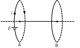
Consider loops A and B placed coaxially as above. Let the direction of the current in loop A be clockwise when a battery is connected to it. According to the right-hand screw rule, the direction of the magnetic field due to this current will be towards left. Now, the current through this loop will decrease with time due to increase in resistance with temperature. So, the magnetic field due to this current will also decrease with time. This changing current will induce current in loop B. Now, according to Lenz's law, the direction of the induced current in loop B will be such that it will oppose the decrease in the magnetic field due to loop A. Hence, current will be induced in clockwise direction in loop B. Also, because the direction of the currents in the loops is the same, they will attract each other.
Page No 305:
- Qstn #11A small, conducting circular loop is placed inside a long solenoid carrying a current. The plane of the loop contains the axis of the solenoid. If the current in the solenoid is varied, the current induced in the loop is
(a) clockwise
(b) anticlockwise
(c) zero
(d) clockwise or anticlockwise depending on whether the resistance is increased or decreased.digAnsr: cAns : (c) zero
The magnetic field inside the solenoid is parallel to its axis. If the plane of the loop contains the axis of the solenoid, then the angle between the area vector of the circular loop and the magnetic field is zero. Thus, the flux through the circular loop is given by
`` \varphi =BA\,\mathrm{\,cos\,}\theta =BA\,\mathrm{\,cos\,}0°=BA``
Here,
B = Magnetic field due to the solenoid
A = Area of the circular loop
θ = Angle between the magnetic field and the area vector
Now, the induced emf is given by
`` e=-\frac{d\varphi }{dt}``
`` \because \phi =BA=\,\mathrm{\,constant\,}``
`` \therefore e=0``
We can see that the induced emf does not depend on the varying current through the solenoid and is zero for constant flux through the loop. Because there is no induced emf, no current is induced in the loop.
Page No 305:
- Qstn #12A conducting square loop of side l and resistance R moves in its plane with a uniform velocity v perpendicular to one of its sides. A uniform and constant magnetic field B exists along the perpendicular to the plane of the loop as shown in figure. The current induced in the loop is
(a) Blv/R clockwise
(b) Blv/R anticlockwise
(c) 2Blv/R anticlockwise
(d) zero.
FiguredigAnsr: dAns : (d) zero
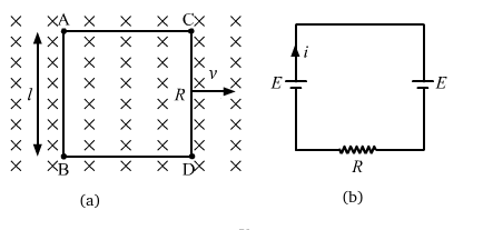
Figure
(a) shows the square loop moving in its plane with a uniform velocity v.
Figure
(b) shows the equivalent circuit.
The induced emf across ends AB and CD is given by
`` E=Bvl``
On applying KVL in the equivalent circuit, we get
`` E-E+iR=0``
`` \Rightarrow i=0``
No current will be induced in the circuit due to zero potential difference between the closed ends.
Page No 305: