CBSE-XI-Physics
31: Capacitors
Note: Please signup/signin free to get personalized experience.
Note: Please signup/signin free to get personalized experience.
10 minutes can boost your percentage by 10%
Note: Please signup/signin free to get personalized experience.
- #Section : i
- Qstn #1Suppose a charge +Q1 is given to the positive plate and a charge -Q2 to the negative plate of a capacitor. What is the “charge on the capacitor”?Ans :

Given:
Charge on the positive plane = +Q1
Charge on the negative plate = `` -``Q2
To calculate: Charge on the capacitor
Let ABCD be the Gaussian surface such that faces AD and BC lie inside plates X and Y, respectively.
Let q be the charge appearing on surface II. Then, the distribution of the charges on faces I, III and IV will be in accordance with the figure.
Let the area of the plates be A and the permittivity of the free space be`` {\in }_{0}``.
Now, to determine q in terms of Q1 and Q2, we need to apply Gauss's law to calculate the electric field due to all four faces of the capacitor at point P. Also, we know that the electric field inside a capacitor is zero.
Electric field due to face I at point P, E1 = `` \frac{{Q}_{1}-q}{2{\in }_{0}A}``
Electric field due to face II at point P, E2 = `` \frac{+q}{2{\in }_{0}A}``
Electric field due to face III at point P, E3 = `` \frac{-q}{2{\in }_{0}A}``
Electric field due to face IV at point P, E4 = `` -\left(\frac{-{Q}_{2}+q}{2{\in }_{0}A}\right)`` (Negative sign is used as point P lies on the LHS of face IV.)
Since point P lies inside the conductor,
E1 + E2 + E3 + E4 = 0
∴ Q1 `` -`` q + q `` -`` q `` -`` (`` -``Q2 + q ) = 0
`` \Rightarrow ``q = `` \frac{{Q}_{1}+{Q}_{2}}{2}``
Thus, the charge on the capacitor is `` \frac{{Q}_{1}+{Q}_{2}}{2}``, which is the charge on faces II and III.
Page No 163:
- Qstn #2As
C=1V Q,can you say that the capacitance C is proportional to the charge Q?Ans : No. Since capacitance is a proportionality constant, it depends neither on the charge on the plates nor on the potential. It only depends upon the size and shape of the capacitor and on the dielectric used between the plates.
The formula that shows its dependence on the size and shape of the capacitor is as follows:
C = `` \frac{{\in }_{0}A}{d}``
Here, A is the area of the plates of the capacitor and d is the distance between the plates of the capacitor.
Page No 163:
- Qstn #3A hollow metal sphere and a solid metal sphere of equal radii are given equal charges. Which of the two will have higher potential?Ans : The potential of a metal sphere is directly proportional to the charge q given to it and inversely proportional to its radius r.
i.e. `` V=\frac{q}{4\,\mathrm{\,\pi \,}{\in }_{0}r}``
Since both the spheres are conductors with the same radius and charge, the charge given to them appears on the surface evenly. Thus, the potential on the surface or within the sphere will be the same, no matter the sphere is hollow or solid.
Page No 163:
- Qstn #4The plates of a parallel-plate capacitor are given equal positive charges. What will be the potential difference between the plates? What will be the charges on the facing surfaces and on the outer surfaces?Ans : It is given that the plates of the capacitor have the same charges. In other words, they are at the same potential, so the potential difference between them is zero.

Let us consider that the charge on face II is q so that the induced charge on face III is `` -``q and the distribution is according to the figure.
Now, if we consider Gaussian surface ABCD, whose faces lie inside the two plates, and calculate the field at point P due to all four surfaces, it will be
E1`` =\frac{Q-q}{2{\in }_{0}A}``
E2 = `` \frac{q}{2{\in }_{0}A}``
E3 = _`` \frac{q}{2{\in }_{0}A}``
E4 =_ `` \frac{Q+q}{2{\in }_{0}A}`` (It is `` -``ve because point P is on the left side of face IV.)
Now, as point P lies inside the conductor, the total field must be zero.
∴ E1 + E2 + E3 + E4 = 0
or
Q `` -`` q + q `` -`` q + Q + q = 0
∴ q = 0
Hence, on faces II and III, the charge is equal to zero; and on faces I and IV, the charge is Q.
Thus, it seems that the whole charge given is moved to the outer surfaces, with zero charge on the facing surfaces.
Page No 163:
- Qstn #5A capacitor has capacitance C. Is this information sufficient to know what maximum charge the capacitor can contain? If yes, what is this charges? If no, what other information is needed?Ans : No. This information is not sufficient. Since the charge is proportional to the potential difference across the capacitor, we need to know the potential difference applied across the capacitor.
q `` \propto `` V `` \Rightarrow ``q = CV
Here, q is the charge, V is the potential difference applied and C is the proportionality constant, i.e. capacitance.
Page No 163:
- Qstn #6The dielectric constant decreases if the temperature is increased. Explain this in terms of polarization of the material.Ans : The amount of polarisation can be understood as the extent of perfect alignment of the molecules of a dielectric with an external electric field. The more aligned the molecules are with the external magnetic field, the more is the polarisation and the more will be the dielectric constant.
But with increase in temperature, the thermal agitation of the molecules or the randomness in their alignment with the field increases.
Thus, we can say that increase in temperature results in reduced polarisation and reduced dielectric constant.
Page No 163:
- Qstn #7When a dielectric slab is gradually inserted between the plates of an isolated parallel-plate capacitor, the energy of the system decreases. What can you conclude about the force on the slab exerted by the electric field?Ans : As the energy of the system decreases, the change in the energy is negative.
Force is defined as a negative rate of change of energy with respect to distance.
F = `` -\frac{\partial U}{\partial x}``
So, as the energy decreases, the force due to the electric field of the capacitor increases when the dielectric is dragged into the capacitor.
Page No 164:
- #Section : ii
- Qstn #1A capacitor of capacitance C is charged to a potential V. The flux of the electric field through a closed surface enclosing the capacitor is
(a)
CVε0
(b)
2 CVε0
(c)
CV2ε0
(d) zero.digAnsr: dAns : (d) zero

Since the net charge enclosed by the Gaussian surface is zero, the total flux of the electric field through the closed Gaussian surface enclosing the capacitor is zero.
`` \Phi =∯E.ds=\frac{q}{{\in }_{0}}``= 0
Here,
`` \Phi `` = Electric flux
q = Total charge enclosed by the Gaussian surface.
Page No 164:
- Qstn #2Two capacitors each having capacitance C and breakdown voltage V are joined in series. The capacitance and the breakdown voltage of the combination will be
(a) 2 C and 2 V
(b) C/2 and V/2
(c) 2 C and V/2
(d) C/2 and 2 V.digAnsr: dAns : (d) C/2 and 2V
Since the voltage gets added up when the capacitors are connected in series, the voltage of the combination is 2V.
Also, the capacitance of a series combination is given by
`` \frac{1}{{C}_{\,\mathrm{\,net\,}}}=\frac{1}{{C}_{1}}+\frac{1}{{C}_{2}}``
Here,
Cnet = Net capacitance of the combination
C1 = C2 = C
∴ Cnet = `` \frac{C}{2}``
Page No 164:
- Qstn #3If the capacitors in the previous question are joined in parallel, the capacitance and the breakdown voltage of the combination will be
(a) 2 C and 2 V
(b) C and 2 V
(c) 2 C and V
(d) C and V.digAnsr: cAns : (c) 2C and V
In a parallel combination of capacitors, the potential difference across the capacitors remain the same, as the right-hand-side plates and the left-hand-side plates of both the capacitors are connected to the same terminals of the battery. Therefore, the potential remains the same, that is, V.
For the parallel combination of capacitors, the capacitance is given by
Ceq = C1 + C2
Here,
C1 = C2 = C
∴ Ceq = 2C
Page No 164:
- Qstn #4The equivalent capacitance of the combination shown in figure (31-Q1) is
(a) C
(b) 2 C
(c) C/2
(d) none of these.
Figure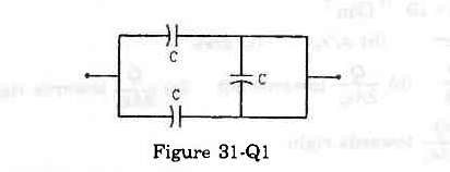 digAnsr: bAns : (b) 2C

Since the potential at point A is equal to the potential at point B, no current will flow along arm AB. Hence, the capacitor on arm AB will not contribute to the circuit. Also, because the remaining two capacitors are connected in parallel, the net capacitance of the circuit is given by
Ceq = C + C = 2C
Page No 164:
- Qstn #5A dielectric slab is inserted between the plates of an isolated capacitor. The force between the plates will
(a) increase
(b) decrease
(c) remain unchanged
(d) become zero.digAnsr: cAns : (c) remain unchanged
The force between the plates is given by
F = `` \frac{{q}^{2}}{2{\in }_{0}A}``
Since the capacitor is isolated, the charge on the plates remains constant.
We know that the charge is conserved in an isolated system.
Thus, the force acting between the plates remains unchanged.
Page No 164: