ICSE-X-Physics
Previous Year Paper year:2018
Note: Please signup/signin free to get personalized experience.
Note: Please signup/signin free to get personalized experience.
10 minutes can boost your percentage by 10%
Note: Please signup/signin free to get personalized experience.
- #5-a [3]
- #5-a-iDerive a relationship between S.I. and C.C.S. unit of work.Ans : Relationship between SI and CGS units of work:
Work is force(F) times displacement(d).
$$W = F × d $$
$$CGS units: [F]*[d] = [dyne][cm] = [erg] $$
$$ 1 Newton = 10^5 dyne , 1 m = 100 cm $$
$$ I joule = 1 newton × 1 m = 10^5 dyne × 100 cm = 10^7 erg $$
- #5-a-iiA force acts on a body and displaces it by a distance S in a direction at an
angle . with the direction of force. What should be the value of . to get
the maximum positive work?Ans : Work = force (F) × displacement in the direction of force
``Work = F × S × \cos \theta ``
Here ``\theta`` is the angle between force F and displacement S.
Hence to get maximum work, ``\cos \theta = 1``
Or `` \theta = 0``
- #5-b [3]
A half metre rod is pivoted at the centre with two weights of ``\pu{20gf}`` and ``\pu{12gf}``
suspended at a perpendicular distance of ``\pu{6 cm}`` and ``\pu{10 cm}`` from the pivot
respectively as shown below.
 Ans :
Ans :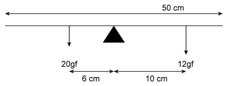
- #5-b-iWhich of the two forces acting on the rigid rod causes clockwise
moment?Ans : ``\pu{12 gf}`` acting on the rigid rod causes clockwise moment.
- #5-b-iiIs the rod in equilibrium?Ans : Yes, the rod is in equilibrium because both clockwise and anti-clockwise
moments are the same.
- #5-b-iiiThe direction of ``\pu{20 kgf}`` force is reversed. What is the magnitude of the
resultant moment of the forces on the rod?Ans : If ``\pu{20 gf}`` is reversed, both forces give clockwise moment.
Total clockwise moment is $$\pu{ 2 × 120 × 9.8 × 10^{−3} Nm = 2.352 Nm}$$
- #5-c [4]
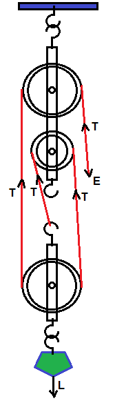
- #5-c-iDraw a diagram to show a block and tackle pulley system having a
velocity ratio of 3 marking the direction of load(L), effort(E) and
tension(T).Ans : Diagram of a block and tackle pulley system with a velocity ratio of 3
marking the direction of load (L), effort (E) and tension (T).
- #5-c-iiThe pulley system drawn lifts a load of ``\pu{150 N}`` when an effort of ``\pu{60N}`` is
applied. Find its mechanical advantage.Ans : Mechanical Advantage = Load/Effort = 150/60 = 2.5
- #5-c-iiiIs the above pulley system an ideal machine or not?Ans : Although theoretical efficiency is 100% for the block and tackle system of
pulleys, mechanical advantage decreases due to friction in the bearings
of the pulleys and the weight of the string and the lower block with
pulleys. Efficiency decreases if mechanical advantage decreases.
- #6
- #6-a [3]
A ray of light X Y passes through a right angled isosceles prism as shown
below.
 Ans :
Ans :A ray of light XY passes through a right angled isosceles prism as shown
below.
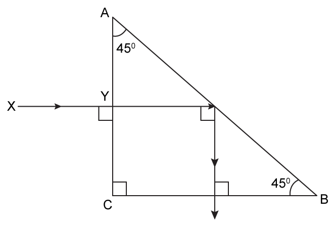
- #6-a-iWhat is the angle through which the incident ray deviates and emerges
out of the prism?Ans : The angle of deviation is 90°.
- #6-a-iiName the instrument where this action of prism is put into use.Ans : This action of the prism is used in periscopes.